I’m currently wrapping up a lot of projects, preparing to start a new chapter of my programming journey next week. Barring procrastination expect an influx of blog posts!
Why you need this blog post#
On my time for the VEX AI Robotics team 3151A, I used the LemLib library for the PROS kernel for my motions and localization. LemLib and similar solutions are often referred to in the VEX community as “templates;” they abstract away significant amounts of functionality (namely, LemLib handles the implementations of motion control and odometry) in exchange for a drastically simpler API.

Hundreds if not thousands of VEX teams use libraries similar to Lemlib to handle motion controls for them. Unfortunately, many competitors, including myself, don’t understand the algorithms behind motion control.
Disclaimer: I’m no expert in control theory! The closest I’ve gotten to LemLib is a single open PR, so take my words with a grain of salt.
Unfortunately, a rare Q&A asked and answered by the VEX Game Design Committee recently stated that:
It is the responsibility of each Team to be able to explain and defend the design, construction, and programming of their Robot if questioned by referees, inspectors, Event Partners, or judges. Teams should be prepared to describe their design process, justify design decisions, and demonstrate a full understanding of how their Robot functions.
In other words, V5RC teams need to be able to explain the programming of their robots.
This can be taken to the extreme, as the rule (and the corresponding RECF Code of Conduct) are quite ambiguous.
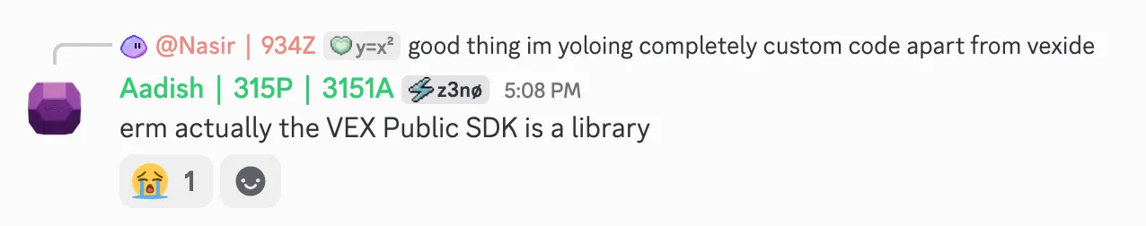 *Exhibit A. Background: vexide relies on a VEX SDK jumptable to do basically anything with the brain.*
 *Exhibit B. Background: created by a vexide maintainer. You can only explain all your code if you wrote the bootloader!*
Anyways, assuming we have to adhere to rule <G3> (Use Common Sense), this means that all teams using LemLib need to be able to explain what each of their calls to LemLib does. Like I previously said, however, many teams aren’t able to do so! In this blog post, I’ll try to explain how most of the LemLib motions work.
Prelude: a brief overview of PID#
Before we continue, a necessary prerequisite is understanding PID control. You can get much better overviews elsewhere but I’ll recap here for reference.
PID stands for “Proportion / Integral / Derivative” control, and its goal is to, given an error, return an “output” force which can be applied to reduce the error. They can basically be thought of as a function:
TL;DR:
- Track your previous error and the sum (integral) of all past errors.
- PID contains three components:
- a component proportional to the error. if there’s more error, increase the force.
- a component proportional to the derivative (basically the change in error). if the error is increasing quickly, move quicker; if its decreasing rapidly, slow down a bit (to avoid overshooting).
- a component proportional to the sum. if it’s been constant error for a long time (i.e., the error is stuck), integral increases and we slowly build up force.
PIDs are designed to be used in a wide range of systems, so there needs to be some way to tune them for different cases, leading to the constants. There are easily available guides online to find how to tune them to optimize the speed and accuracy of your PID, but those are beyond the scope of this part.
LemLib’s implementation of PID is actually quite simple to understand (only 20 lines!); I highly suggest taking a look to better understand how PID is actually implemented.
PID is everywhere!#
PID underlies most of LemLib’s motion algorithms. All angular motions (turnToHeading, turnToPoint, and their swingToHeading/swingToPoint counterparts) rely almost entirely on a PID. They compare the robot’s current heading to the target angle to get an error which is fed into the controller. For turnToPoint and swingToPoint, the target angle is calculated from the target point using ✨math✨.
LemLib’s moveToPoint implementation is more complex, however. It still uses PID, but with a few other components to have a fast, arc-like curve. I’ll explore a bit more about how it is implemented in this next section.
How moveToPoint works#
Let’s go back to the beginning. I want to implement move to point. There are two requirements: it should be accurate and fast. If it’s inaccurate, we’re not actually going to the right point. If it’s slow, oops! - I just wasted all of the autonomous period going to a single block. I’ll explain each step using Rust-like pseudocode. We’ll organize our code into levels, starting with the simplest implementation and building up to the full implementation.
Level 0: Let’s say we’re pointing at the target point already. That’s great!

We want to drive straight forward until we reach the target point — in other words, we want to minimize the distance between the robot and the target point. If we call this distance the “error,” it becomes clear that a PID controller is applicable here! To calculate the error, we can use the distance formula (Khan Academy reference). Our code so far looks like this:
// constants:
// maxError: the maximum error you allow for the distance
fn moveToPoint(targetPoint) {
    while error > maxError {
        let error = distance(robot, targetPoint);
        let output = computePID(error);
        driveForward(output);
    }
}
We use a maxError to let the controller know when it can safely exit; think of it as a way to tune the accuracy/speed balance. If you want to be within 5 units of your target, set maxError to 5, etc.
There’s a slight issue though: we might not be already pointing at the target. If we are even 1 degree off from the target, we’ll drive right past it and never settle, since the output will always be positive (leading to us constantly driving forward) if we aren’t close enough to the target.
Level 1. Level 0 was mostly warm-up to understand PID and how to use the distance formula; let’s go through actually feasible solutions. The simplest solution to allow us to handle targets with different angles is just to first point at the target, then reuse our code from Level 0. This basically involves running an initial PID to first get us pointing at the target, then another PID (the same as we used in Level 0) to drive to it. These are referred to as the “angular PID” and “lateral PID”, respectively.
“Lateral” is a kinda misleading term! It actually means “sideways,” but has kinda been hijacked by control theorists to refer to any straightforward motion.
Here’s a diagram, with the angular error annotated:
// we now have two PID functions: computeLateralPID and computeAngularPID
// constants:
// maxLateralError: the maximum error you allow for the distance
// maxAngularError: the maximum error you allow for the angle before we start driving to the target
fn moveToPoint(targetPoint) {
while abs(angularError) > maxAngularError {
// assume angularError is from -180º - 180º
let angularError = angleFrom(robot, targetPoint);
let output = computeAngularPID(angularError);
driveTurn(output);
}
while error > maxLateralError {
let error = distance(robot, targetPoint);
let output = computeLateralPID(error);
driveForward(output);
}
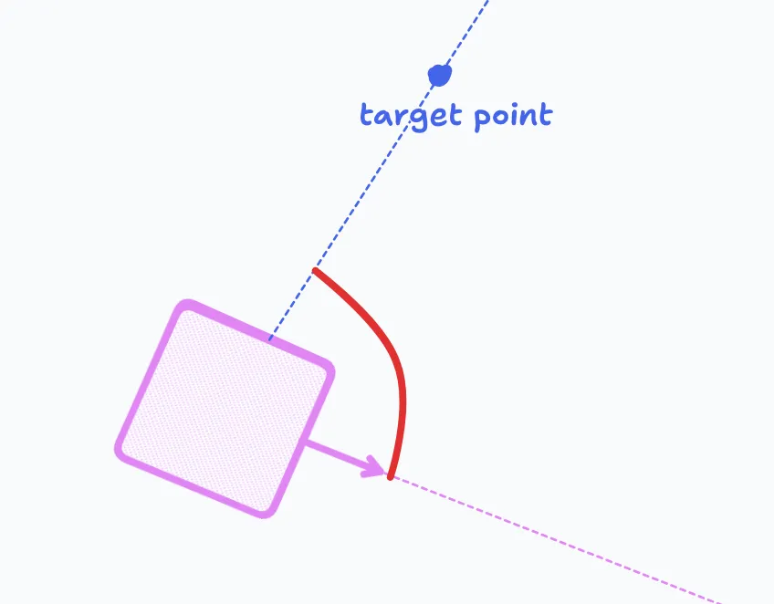
}This is already a massive improvement, since we’ll probably get somewhere close to the target (hopefully!). However, if there is an obstacle on the route, or if we aren’t pointing exactly at the target, or if the drivetrain has drift/is overheating, etc., we might end up skewing sideways! Here’s an example of such a “near miss:”
Level 2. What if we detected when we starting to deviate from our path? Then, we could stop, turn to the point again, and continue.
But how would we determine if we’ve from the path? Doing so is actually a nontrivial process. One option is that we could recalculate angularError = angleFrom(robot, targetPoint), but that would require tuning another constant, like so:
// constants:
// acceptableAngularError: the angular error which is okay from deviations from the path
fn moveToPoint(targetPoint) {
    while lateralError > maxLateralError {
        let deviatedFromPath = angleFrom(robot, targetPoint) > acceptableAngularError;
        if deviatedFromPath {
            while abs(angularError) < maxAngularError {
                // assume angularError is from -180º - 180º
                let angularError = angleFrom(robot, targetPoint);
                let output = computeAngularPID(angularError);
                driveTurn(output);
            }
        }
        let error = distance(robot, targetPoint);
        let output = computeLateralPID(error);
        driveForward(output);
    }
}
That’s annoying to tune, and also not fast; turning, driving, stopping, turning again, etc. is very slow due to the repeated full stops. Time to do some speeding up…
Level 3. What if, instead of doing turns and forward motion in entirely seperate stages, we do them simulatenously?! This sounds weird, but it makes sense if you’ve used arcade drive before. Arcade controllers basically allow us to simulatenously execute turning and straight motion on a tank drivetrain, using the following:
fn driveArcade(straight, turn) {
    moveLeftSide(straight + turn);
    moveRightSide(straight - turn);
}
This has an issue which we’ll discuss later, but it makes combining the two motions trivially; we can
- calculate angular and lateral error
- plug them in to our respective PIDs to get angular and lateral velocity commands
- plug those into our arcade function to get left and right motor commands and move the drivetrain.
fn moveToPoint(targetPoint) {
    while lateralError > maxLateralError {
        let lateralError = distance(robot, targetPoint);
        let lateralOutput = computeLateralPID(lateralError);
        let angularError = angleFrom(robot, targetPoint);
        let angularOutput = computeAngularPID(angularError);
        driveArcade(lateralOutput, angularOutput);
    }
}
This looks great! Now, we can start moving forward even while we are still turning towards the target point. This produces the expected smooth curving motion. Also, since we’re always running the angular PID, the above issue is addressed; angular error at any point in the motion is immediately resolved.
Is this the holy grail of move to point algorithms? No…
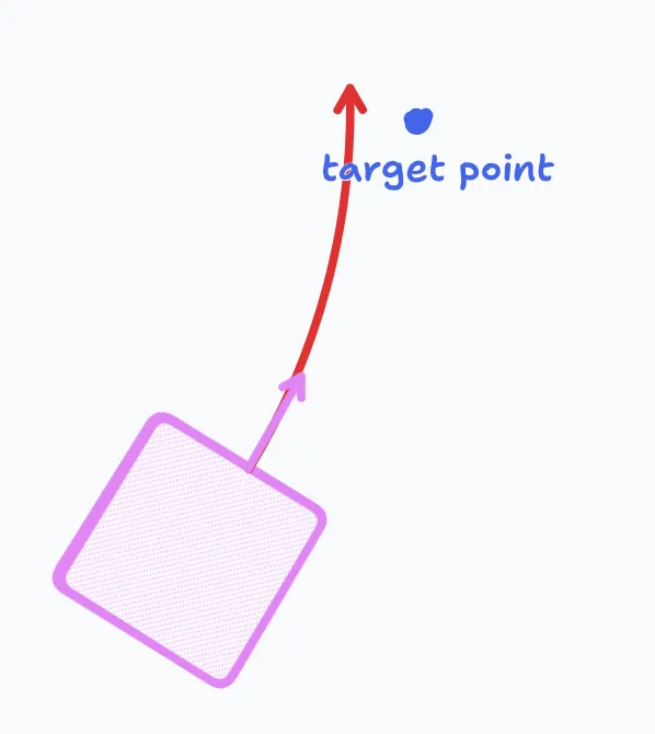
Suppose we have a robot that’s facing about 90 degrees away from the target point. Initially, going forward at all would be a bad idea since it actually brings the robot farther away from the targt. Unfortunately, our moveToPoint function doesn’t know that, so it starts driving forward. It thus takes a lot longer for the turn to execute and redirect the robot all the way back. An example of the resulting elongated arc motion is below, with the ideal curve in light blue.
Level 4. Ideally, we’d decrease the lateral PID output if the robot is facing too far away from the target point. To do this, we can make a minor yet very helpful modification to our code for Level 3. Instead of using the raw distance to the target as the lateral error, we multiply the raw distance by the cosine of the angular error.
This may sound arbitrary, but it makes sense when you consider the behavior of the cosine function: when the input (a.k.a. angular error) is near 0, cosine is near 1, so when the robot is pointing pretty close to the target, the lateral error is higher and it can start driving forward faster. If the input is closer to 90º, cosine is near 0, so the robot will slow down if it needs to turn.
Note that, if the angular error is obtuse, the cosine is negative. This is unintended as it will negate the lateral error, leading to the robot driving backward. A key guarantee of LemLib’s moveToPoint implementation is that it only ever moves forward (unless the reversed flag is set, of course), so we just set lateralError is 0 if the angular error is negative — in other words, we don’t start driving forward until we are at most facing 90 degrees away from the target.
And our updated code:
fn moveToPoint(targetPoint) {
    while lateralError > maxLateralError {
        let angularError = angleFrom(robot, targetPoint);
        let angularOutput = computeAngularPID(angularError);

        let lateralError = distance(robot, targetPoint) * cos(angularError);
        if abs(angularError) > 90º {
            lateralError = 0;
        }
        let lateralOutput = computeLateralPID(lateralError);

        driveArcade(lateralOutput, angularOutput);
    }
}
This is commonly known as cosine scaling.
This is great! We now have super smooth, curving arc motions that go straight to our target point. Alas, there are still myriad edge cases that we need to consider.
Level 5. Let’s look back at our arcade function:
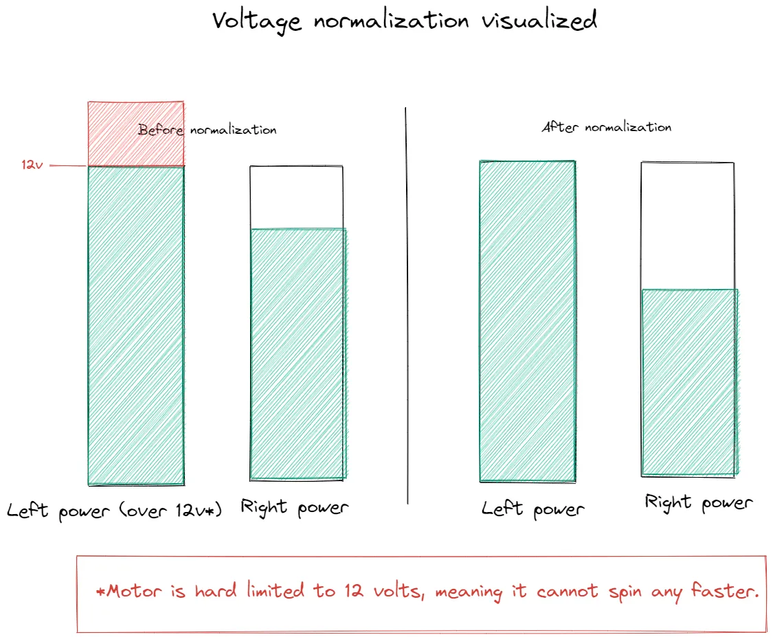
There is a subtle bug here, known as oversaturation. If both straight and turn are very high (close to the maximum motor power), the input to moveRightSide (or moveLeftSide, if turn is very large) will be greater than the maximum motor power. This won’t break the motors (luckily), but it will cause the powers to get clamped to the maximum. This leads to the turn amount being less than expected. To avoid this, we can scale down (desaturate) both side’s power if either is too large. This way, even if the robot moves a bit slower, the turning radius will be more accurate. Here’s a helpful diagram from a LemLib issue:
The change looks like this:
fn driveArcade(straight, turn) {
    let left = straight + turn;
    let right = straight - turn;
    let max = max(abs(left), abs(right));
    if max > MAXIMUM_MOTOR_POWER {
        left *= MAXIMUM_MOTOR_POWER / max;
        right *= MAXIMUM_MOTOR_POWER / max;
    }
    moveLeftSide(left);
    moveRightSide(right);
}
(No changes to moveToPoint are required.)
LemLib has an equivalent desaturate function used in their move to point implementation.
One bug squashed… just one more to go.
Level 6. If you played around enough with the above cosine scaling widget, you might have noticed something peculiar: if the robot is very close to the target point, any slight movement can result in drastic changes to the angular error. The closer the robot gets, the more unreliable turning is. By the time we get to the target point, the robot is basically turning unpredictably. This is obviously not good.
There are a bunch of interesting ways to address this, but the simplest is to disable turning when the robot is within a certain threshold distance of the target point. The implementation is relatively simple. We set angularError to zero instead of angularOutput so that the cosine scaling doesn’t get messed up either:
// constants:
// stopTurningError: the distance at which to effectively disable turning. in LemLib, this is set to 7.5in.
fn moveToPoint(targetPoint) {
    while lateralError > maxLateralError {
        let angularError = angleFrom(robot, targetPoint);
        if distance(robot, targetPoint) < stopTurningError {
            angularError = 0;
        }
        let angularOutput = computeAngularPID(angularError);

        let lateralError = distance(robot, targetPoint) * cos(angularError);
        if abs(angularError) > 90º {
            lateralError = 0;
        }
        let lateralOutput = computeLateralPID(lateralError);

        driveArcade(lateralOutput, angularOutput);
    }
}
These together form the key components of LemLib’s move to point implementation. To summarize, the final implementation involves:
- Combined lateral and angular PIDs,
- with lateral output scaled by the cosine of angular error,
- with angular output disabled when lateral error is below a threshold,
- combined via a desaturating arcade function.
Let’s see how LemLib does it.
Code walkthrough#
The LemLib code is pretty verbose and uses a lot of LemLib-specific utils. If you feel overwhelmed, refer back to the above pseudocode.
LemLib is weird#
This code might not look like any C++ code you’ve seen or written before. There are a few important things to understand before looking at it:
- LemLib has its own ecosystem of internal tooling (loggers, utility classes, etc.) that are used everywhere. I’ll skip over most of these since they aren’t helpful and just focus on the math/logic.
- LemLib is infinitely configurable, so it supports a large number of customizable parameters for the move to point implementation:
params.forwards— false if the robot is only allowed to go backwards. If false, modifications are made to the math so that it works for going in reverse.lateralSmallExitandlateralLargeExitare instances of a LemLibExitConditionclass, which basically say wait until the error is below a certain threshold for a certain amount of time. Furthermore, there is also atimeoutparam. Why do we need three different ways of figuring out when to exit?!lateralSmallExitwaits until the lateral error is below a small threshold for a short amount of time.lateralLargeExitwaits until the lateral error is below a large threshold for a large amount of time. This is basically in case, for some reason, the robot get stucks at a particular error; e.g., maybe there is an obstacle preventing it from getting close enough to trigger thelateralSmallExit.- Finally,
timeoutis a last resort; it’s a (generally much larger) time after which, no matter what the error is, the motion exits. This is a safety measure in case something goes terribly wrong during the execution of the motion.
params.earlyExitRange: this basically says “stop once I’mearlyExitRangeaway from the target.” This is commonly used in motion chaining, where multiple motions are executed consecutively with smooth transitions (no stops) between them (learn more on the LemLib docs). For regular motions, it is set by default to 0 inches (“only stop if I am exactly at the target, or have overshot it”).
- All speed values are from
-127 <-> 127, since that is what PROS motors natively take as input voltage.
Setup#
This is boilerplate, don’t worry too much about. The rest of our code will occur inside the moveToPoint function.
Permalink to the code I discuss
#include <cmath>
#include "lemlib/chassis/chassis.hpp"
#include "lemlib/logger/logger.hpp"
#include "lemlib/timer.hpp"
#include "lemlib/util.hpp"
#include "pros/misc.hpp"

void lemlib::Chassis::moveToPoint(float x, float y, int timeout, MoveToPointParams params, bool async) {
    params.earlyExitRange = fabs(params.earlyExitRange);
    this->requestMotionStart();
    // were all motions cancelled?
    if (!this->motionRunning) return;
    // if the function is async, run it in a new task
    if (async) {
        pros::Task task([&]() { moveToPoint(x, y, timeout, params, false); });
        this->endMotion();
        pros::delay(10); // delay to give the task time to start
        return;
    }

    // reset PIDs and exit conditions
    lateralPID.reset();
    lateralLargeExit.reset();
    lateralSmallExit.reset();
    angularPID.reset();

    // ...this is where the rest of our discussed code will live

    // stop the drivetrain
    drivetrain.leftMotors->move(0);
    drivetrain.rightMotors->move(0);
    // set distTraveled to -1 to indicate that the function has finished
    distTraveled = -1;
    this->endMotion();
}
Pretty simple; we add imports, declare the function, and brake at the end. There’s a lot of boilerplate to handle LemLib’s way of managing motions and handle an edge case, but don’t worry too much about it. Let’s look at the rest:
Boilerplate (persistent variables & main loop)#
// initialize vars used between iterations
Pose lastPose = getPose();
distTraveled = 0;
Timer timer(timeout);
bool close = false;
float prevLateralOut = 0; // previous lateral power
float prevAngularOut = 0; // previous angular power
const int compState = pros::competition::get_status();
std::optional<bool> prevSide = std::nullopt;
These variables keep track of various things throughout the loop’s iterations:
- the
timeris a LemLib utility that’s used to break the loop when the motion is cancelled or the timer is done. closeis a variable which is set to true once we are within a certain threshold distance (in this case,7.5 inches) of the target. This is analogous to the check we do in Level 6, and is later used to disable turning when the robot is close.distTraveledis a global variable in LemLib used to keep track of the progress of motions. Here, we reset it in preparation for beginning the new motion.prevLateralOutandprevAngularOutsimply store the previous lateral and angular PID outputs.lastPosesimilarly stores the last pose the robot was at.prevSideis anoptional<bool>, which means it has three states:nullopt,true, andfalse. We basically use the boolean options as a way to show which “side” of the target point we are on, and the null state is just a placeholder for until we run an iteration. I’ll explain more in the relevant part of the loop.- Don’t worry about
compState, it’s not used anywhere else.
The rest of our code occurs inside the loop body:
while (!timer.isDone() && ((!lateralSmallExit.getExit() && !lateralLargeExit.getExit()) || !close) &&
       this->motionRunning) {
    // ...
}
Basically, we loop while all of these conditions are true:
- we haven’t run out of time
- our motion is still running
- we haven’t gotten close to the target OR neither exit condition has triggered
Let’s see what happens inside the loop.
Calculating close#
// update position
const Pose pose = getPose(true, true);

// update distance traveled
distTraveled += pose.distance(lastPose);
lastPose = pose;

// calculate distance to the target point
const float distTarget = pose.distance(target);

// check if the robot is close enough to the target to start settling
if (distTarget < 7.5 && close == false) {
    close = true;
    params.maxSpeed = fmax(fabs(prevLateralOut), 60);
}
There’s some more boilerplate:
- getting the pose of the robot,
- getting the distance of its pose to the current pose,
- and updating the global vars
distTraveledandlastPose.
The if statement, however, is quite interesting. This isn’t to disable turning like we discussed in Level 6, but rather just something to avoid the robot speeding up too much in the final leg (like if it overshoots). It limits lateral and angular motion to either 60/127 ≈ 47% power, or the previous lateral output, whichever is larger. We incorporate the previous lateral output to avoid sudden deceleration — if the previous lateral output was 100% (127) then capping it to 60 would be like slamming on the brakes. As noted in the comment, this helps the robot “settle” into the target position. The close variable represents whether the robot is settling or now. Note that params.maxSpeed affects both the angular and linear outputs.
Early (and regular) exit#
// motion chaining
const bool side =
    (pose.y - target.y) * -sin(target.theta) <= (pose.x - target.x) * cos(target.theta) + params.earlyExitRange;
if (prevSide == std::nullopt) prevSide = side;
const bool sameSide = side == prevSide;
// exit if close
if (!sameSide && params.minSpeed != 0) break;
prevSide = side;
That prevSide variable we previously discussed comes into play here. The equation on the second line is quite complex — I’ve added a Desmos visualization below to help visualize the inequality. I’ve set params.earlyExit to 1 — it would typically be 0, meaning the line of the inequality goes through the target point.
The rest of the code is relatively simple logic: if we’ve switched sides (i.e., crossed the line), that’s an indicator it’s time to stop, so we break out of the loop. This makes sense intuitively; if we’ve crossed the line, that means we’re params.earlyExit inches or closer to the target point, so it’s a good time to stop. (It might also be that we’ve overshot the target point, in which case it is also a good time to stop.)
Calculating error and controller outputs#
This is quite a big chunk of code, but each part on its own is quite simple!
// calculate error
const float adjustedRobotTheta = params.forwards ? pose.theta : pose.theta + M_PI;
const float angularError = angleError(adjustedRobotTheta, pose.angle(target));
float lateralError = pose.distance(target) * cos(angleError(pose.theta, pose.angle(target)));

// update exit conditions
lateralSmallExit.update(lateralError);
lateralLargeExit.update(lateralError);

// get output from PIDs
float lateralOut = lateralPID.update(lateralError);
float angularOut = angularPID.update(radToDeg(angularError));
if (close) angularOut = 0;

// apply restrictions on angular speed
angularOut = std::clamp(angularOut, -params.maxSpeed, params.maxSpeed);
angularOut = slew(angularOut, prevAngularOut, angularSettings.slew);

// apply restrictions on lateral speed
lateralOut = std::clamp(lateralOut, -params.maxSpeed, params.maxSpeed);
// constrain lateral output by max accel
// but not for decelerating, since that would interfere with settling
if (!close) lateralOut = slew(lateralOut, prevLateralOut, lateralSettings.slew);

// prevent moving in the wrong direction
if (params.forwards && !close) lateralOut = std::fmax(lateralOut, 0);
else if (!params.forwards && !close) lateralOut = std::fmin(lateralOut, 0);

// constrain lateral output by the minimum speed
if (params.forwards && lateralOut < fabs(params.minSpeed) && lateralOut > 0) lateralOut = fabs(params.minSpeed);
if (!params.forwards && -lateralOut < fabs(params.minSpeed) && lateralOut < 0)
    lateralOut = -fabs(params.minSpeed);

// update previous output
prevAngularOut = angularOut;
prevLateralOut = lateralOut;

infoSink()->debug("Angular Out: {}, Lateral Out: {}", angularOut, lateralOut);adjustedRobotTheta: we just add π = 180 degrees to the robot’s angle if it is driving in reverse, which makes sense as its front is flipped.angularError&lateralError: the same calculations we did in our pseudocode. You can even see the cosine scaling in action!- We update our exit conditions so they can decide whether it’s time to exit yet.
- As expected, we update our PIDs (with a bit of angle conversions).
- This
ifcheck:
implements the turn disabling we derived in Level 6.if (close) angularOut = 0; - We clamp both outputs to the range of
-maxSpeed <-> maxSpeed. Recall that we also implement settling behavior by settingmaxSpeed. - We apply the
slewfunction. Its exact purpose and implementation aren’t relevant, but it basically prevents sudden acceleration/deceleration. It’s disabled for the lateral output when settling (since we already have special behavior, discussed above, for settling). - There are a few more modifications to the lateral output:
- We apply clamping to ensure we’re going in the right direction. This is somewhat accomplished in our pseudocode by clamping the lateral error, but that assumes the lateral PID function always returns positive outputs for positive inputs; LemLib’s solution is more robust.
- We apply
params.minSpeedaccording using some logic that seems complicated but is actually quite simple. We obviously don’t applyminSpeedto the angular output (since having a “minimum turning speed” is not a good idea!).
- Finally, we update
prevAngularOutandprevLateralOut, and debug the outputs.
TL;DR: we calculate PID errors, then normalize and slew the PID outputs.
Desaturation & wrap-up#
// ratio the speeds to respect the max speed
float leftPower = lateralOut + angularOut;
float rightPower = lateralOut - angularOut;
const float ratio = std::max(std::fabs(leftPower), std::fabs(rightPower)) / params.maxSpeed;
if (ratio > 1) {
    leftPower /= ratio;
    rightPower /= ratio;
}

// move the drivetrain
drivetrain.leftMotors->move(leftPower);
drivetrain.rightMotors->move(rightPower);

// delay to save resources
pros::delay(10);
This part is relatively simple.
The “ratio the speeds” section is analagous to the desaturation we did in Level 5, but uses params.maxSpeed instead of a constant upper limit.
We move the drivetrain accordingly, then sleep a bit to avoid starving the processor. That’s it!
Conclusion#
Hope this helped :D
I might write up another post in this series in the future, focusing on more advanced controllers (boomerang controller, and cross-track error based algos). Let me know if you’d be interested!
Sources#
- 5. Angular Motion | LemLib docs
- 6. Lateral Motion | LemLib docs
- LemLib/src/lemlib/PID.cpp
- LemLib/src/lemlib/motions/moveToPoint.cpp
Thanks to Nasir | 934Z, GrkDev | 23880A, andrew | 781x, and Liam | TNTN (creator of LemLib!) from VTOW for helping me review this post before publication! Image credits for the oversaturation diagram to tropix126 (Nathaniel | AUBIE1 of VTOW) in the linked LemLib issue.
